
How to Control Membrane Fouling Through MBR Aeration
Table of Contents
In the process of MBR membrane filtration, membrane fouling occurs when the transmembrane pressure gradually increases, and the membrane flux decreases due to concentration polarization and filter cake layer formation on the membrane surface.
Membrane fouling control methods mainly include aeration flushing, chemical cleaning, biological control, and electric-assisted decalcification. Among them, aeration flushing has the advantages of simple operation and no secondary pollutants compared with other control methods, which is a critical fouling control method in MBR.
What is the principle of membrane fouling controlled by MBR aeration?
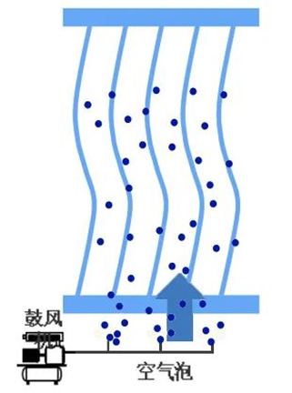
Aeration relies on the agitation of air bubbles to create a cross flow on the membrane surface to generate shear and stirring forces so that bio-concentrates and other macromolecules are separated from the membrane surface under its action, controlling the concentration polarization of the membrane surface and the formation of the filter cake layer, improving the membrane flux and extending the membrane operating cycle.
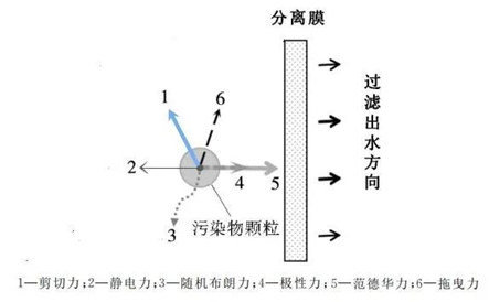
The shear force (shear stress) is mainly determined by the state of air-liquid motion caused by aeration. The average shear stress of aeration on the surface of the hollow fiber membrane consists of three components:
- Shear stress resulting from the local fluid flow state change caused by bubble rising.
- Shear stress resulting from liquid flow due to lateral movement of bubbles.
Shear stress is generated directly by the lateral motion of the bubble.
Since the viscosity of the liquid is much greater than that of air, the control of membrane fouling is mainly based on the first and second points above.
What factors influence MBR aeration?
Several factors affect the fouling of aeration control membranes, including bubble shape, bubble flow pattern, aeration intensity, and aeration mode.
Bubble Shape
In MBR, bubbles can be classified into spherical, ellipsoidal, and spherical caps shaped according to bubble shape. The diameter of a spherical bubble is generally 1.5~3.0mm, rising in a straight line without a tail flow area. The diameter of an ellipsoidal bubble is generally 3.0~10.0mm, growing in a spiral around a vertical axis, with a vortex area at the tail close to the size of the bubble. Finally, the diameter of a spherical cap bubble is generally 10.0~20.0mm, with an apparent oscillation in the rising process and a vortex area at the tail more than twice the size of the bubble.
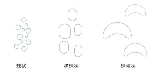
The pore size and aeration volume of the aerator mainly determine bubble shape. The larger size of a spherical bubble can create turbulence in more areas between membranes and increase the shear force. Therefore, appropriate aerator pore size and aeration volume will reduce energy consumption, increase shear force, and reduce membrane fouling by producing spherical cap bubbles.
Bubble flow pattern
In MBR, the bubble flow pattern is determined by the distance between the bubble and the membrane, mainly divided into bubble flow and plunger flow. When the bubble size is much smaller than the membrane spacing, the bubble flow pattern is mostly bubble flow. When the bubble size is close to or larger than the membrane spacing, the bubble flow pattern is mainly plunger flow.
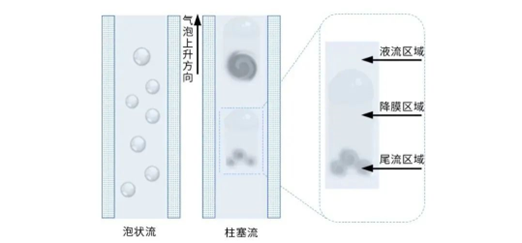
The shear force generated by the different bubble flow patterns is also separate. However, compared with bubble flow, plunger flow can generate more shear force in the falling membrane area because there is no space for the liquid to flip and move, which is beneficial for removing membrane surface fouling. In addition, the intense secondary turbulence in the wake of the plunger flow can also increase the shear force, which can be used for secondary scouring of membrane surface fouling. Therefore, the plunger flow can effectively improve the shear force mainly due to the falling membrane and wake regions.
Aeration intensity
Aeration intensity is one of the essential parameters in MBR operation, which reflects the amount of aeration and is positively correlated with the shear force on the membrane surface. Therefore, if the aeration intensity is low, the hydraulic shear force generated by aeration is insufficient to remove the pollutants on the membrane surface. However, too much aeration will cause the sludge floc to break up and produce many small particles of colloids and dissolved substances, readily adsorbed in the membrane pores and causing more severe membrane fouling.
Aeration mode
The aeration method can be roughly divided into continuous and intermittent. The optimization and selection of the aeration method affect the membrane fouling control effect and significantly impact the reactor energy consumption. Many studies have proved that the membrane flux of intermittent aeration can be maintained longer than continuous aeration, while intermittent aeration is more conducive to saving reactor energy consumption.
What are the effects of MBR aeration on biochemistry?
In MBR, membrane fouling is directly related to microbial growth and metabolism, especially in aerobic membrane bioreactors where aeration provides the dissolved oxygen required for microbial growth. Dissolved oxygen is an essential factor affecting the biochemical properties of the sludge mixture. When the dissolved oxygen content is low, the particle size of the sludge mixture decreases, and the relative molecular weight of soluble microbial products (SMP) increases, thereby increasing the filtration resistance. However, high-intensity aeration leads to sludge lysis, which decreases the particle size of the sludge floc and increases the relative molecular weight of SMP, exacerbating membrane fouling.
Aeration intensity also affects the content of extracellular polymeric substances (EPS), a sticky substance secreted by microbial cells that plays an essential role in sludge floc formation. The total amount of EPS in a reactor with high aeration intensity is relatively high, and the high amount of EPS will bind closely to the membrane in the form of chemical bonds, thus changing the permeability characteristics of the membrane and reducing the filtration flux of the membrane.
Therefore, increasing the aeration within a specific unit reduces membrane fouling, but further expanding it does not help control membrane fouling when it rises to a certain level. Therefore, when the MBR operates under certain operating conditions, a minimum amount of aeration is required to meet the membrane fouling control requirements, i.e., the critical aeration. Determining the critical aeration is important to avoid wasting aeration energy and to improve the economics of operating the MBR system.
What are the key factors of membrane fouling controlled by MBR aeration?
The critical factors for controlling MBR membrane fouling by aeration scouring are as follows:
- Controlling and optimizing the formation of the spherical cap bubble of the plunger flow so that such bubbles can be stably and uniformly distributed in the reactor.
- Optimizing the aeration method and performing intermittent aeration to improve the effect and simultaneously reduce the aeration energy consumption.
- Combine fluid mechanics and biochemical mechanisms to comprehensively determine the appropriate aeration operating conditions to reduce energy consumption and improve efficiency.
How to evaluate the performance of the MBR aeration system?
MBR aeration, an essential means to control membrane fouling, is one of the critical technologies to ensure the regular and stable operation of the MBR system. The MBR aeration system consists of blowers, air piping, valves, instrumentation, and a purging device at the bottom of the membrane tank.
Due to design concepts and patent restrictions, there are specific differences in structural design and performance among manufacturers in the current MBR system. Therefore, how to evaluate the performance of the aeration system is mainly as follows.
Aeration uniformity
Aeration uniformity directly affects the regular operation of the MBR membrane. If the aeration is not uniform, a part of the membrane sheet with small aeration is quickly fouled, and a part of the membrane with large aeration may cause structural loss of membrane filaments due to excessive aeration. The main factors affecting the uniformity of membrane aeration are the installation level of the membrane tank, the aeration strength, and the structural design of the purging device.
Anti-fouling ability
The gas released from the blowing device in the aeration system has a certain temperature. Therefore, under long-term contact with the activated sludge, the activated sludge tends to dry up and accumulate in the aeration pipe, causing the blockage of the aeration pipeline, thus affecting aeration. Therefore, the design of the sludge discharge structure of the blowing device determines the anti-fouling ability of the aeration system.
Aeration energy consumption
The energy consumption of the aeration system accounts for more than 70% of the energy consumption of the whole MBR system. Reducing the aeration energy consumption while ensuring the aeration effect is the core indicator of the performance of the aeration system.
What are the typical types of MBR aeration systems?
MBR aeration system is divided into continuous and intermittent aeration systems according to the operation mode.
Continuous Aeration System
The blowing device in the continuous aeration system must release gas continuously. Its advantages are a simple system structure and low investment cost. Disadvantages are high aeration intensity and high aeration energy consumption.
Intermittent aeration system
The purging device in the intermittent aeration system only needs to release gas intermittently. Therefore, studying surface intermittent aeration can effectively improve the aeration effect and reduce the aeration energy consumption, which is a superior aeration method. At present, intermittent aeration is achieved in two ways:
- Two valves in parallel control the opening time of different aeration pipes to realize the intermittent aeration of the membrane box.
- Through the characteristics of fluid mechanics, a particular pulse-blowing device is used to realize the intermittent aeration of a single aeration box.
The first method of alternating aeration by opening and closing a set of valves is gradually replaced by the second method because the frequent opening and closing of the valve affect its service life.
What are the main types of MBR aeration-blowing devices?
MBR aeration system can be divided into perforated pipe aeration, slot aeration, and large bubble pulse aeration according to the structure of the blowing device.
Perforated pipe aeration
Perforated pipe aeration is currently the most widely used. Its advantages are simple design and low equipment cost. Disadvantages are the risk of fouling and high aeration energy consumption.
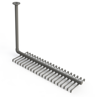
The perforated pipe aeration structure is the main aeration pipe connecting several aeration branch tubes, each with purge holes, sludge discharge holes, or sludge discharge bends. The design points of the perforated pipe aeration are as follows:
- The flow rate of the main aeration pipe is larger than the flow rate of each aeration branch pipe, and the flow rate difference between the branch pipe and the purge hole should be more than six times to ensure uniform air distribution.
- The blowing strength of the hollow fiber membrane is usually 40~150m3/h (calculated by the standard of the projected area of the membrane sheet of the membrane module <upward part>). Therefore, the pore size of the blowing air hole on the blowing pipe should not be less than 3mm, and the hole is easily blocked if it is small. The pore size of the blowing air hole should not be larger than 5mm, and the hole is easily uneven when the blowing gas volume is small.
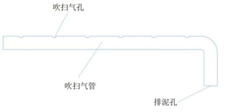
- Mud discharge holes should be placed on the blowing branch pipe, or a mud discharge elbow should be placed at the end to prevent fouling in the aeration pipe.
- There are two designs of blowing air holes: upward and downward. When the design is up, the resistance of the air hole is less, but the gas in the purge tube will float in the upper layer of the mixture. If the purge air hole is too large or the airflow in the purge tube is insufficient, the sludge cannot be discharged entirely because the air in the purge tube is not full, causing some of the air holes to be blocked. When the design is down, the purge airflow first empties the sludge in the purge tube and then overcomes the resistance of the hole before entering the normal purge state. This design is easier to keep the purging air even before and after, but because the hole is down, the initial driving force of the purging air is very large, and a long tail pipe is needed to prevent the airflow from running due to the impact when the purging air starts.
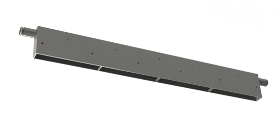
Slot aeration
Slot aeration is an aeration structure that evolved from perforated pipe aeration. The whole is a square slot structure; the bottom is open, and blowing air holes are located on both sides of the slot. It completely solves the problem of sludge fouling and clogging the aeration pipe. However, the principle is still the same as that of perforated pipe aeration, and the air inlet resistance to be overcome is larger, aeration energy consumption is not advantageous compared to perforated pipe aeration.
Large bubble pulse aeration
Large bubble pulse aeration is a device that can provide intermittent large bubbles from the air. This method has a solid stirring ability to the liquid, a good aeration effect, and saves purge gas, which is efficient and energy-saving.
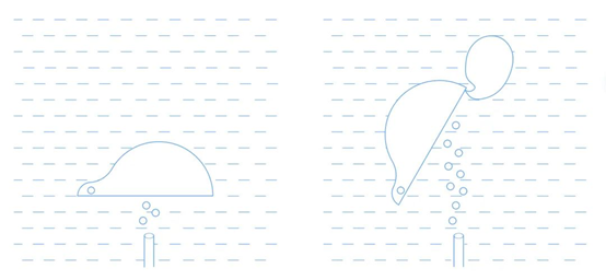
The principle of large bubble formation is simple: a large continuous flow of air is physically aggregated into intermittent large bubbles and released. The form used in the early days is shown in the picture below, where the moving parts attach an air collection hood, inflate the hood, and when the buoyancy exceeds its mass, the hood rotates around the rotation axis, and large bubbles are released.
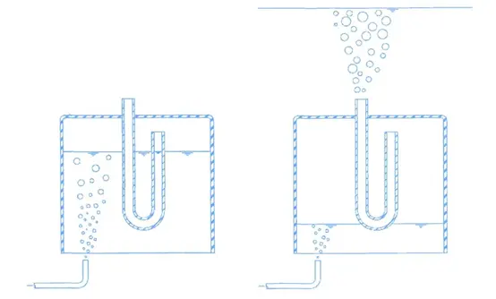
Since there is a higher risk of failure of moving parts in devices that have been in use for years, the shape shown below is most commonly used today. In an inverted gas collection hood, a U-shaped connecting tube is placed, and the hood is submerged in water. When a continuous flow of air from the gas supply tube enters the hood, it pushes out the water inside it and forms a gas chamber. As the gas layer moves down below the bottom edge of the connecting tube, the gas crosses the bottom of the U-shaped tube connected to the left and right, creating an inverted siphon effect, and the gas is immediately released to form large bubbles that enter the bottom of the membrane module. As the bubbles spill over, the water level in the gas collection hood rises and floods the entire U-tube, completing the bubble release process.
At present, most MBR aeration systems in the industry still use continuous operation mode and perforated tube aeration structures. After a large number of experiments and applications show that, compared with the traditional perforated pipe aeration or slot aeration, the use of large bubble intermittent aeration method on the membrane cleaning effect significantly improved, and blowing energy consumption can be reduced by more than 1/3. It is a superior aeration method that will gradually replace the traditional one, and the membrane pollution will be better controlled.